![]()
This guide is about my approach to siting and shaping greens and a technique I developed for mapping slopes. This technique helps me better see what a green looks like and more importantly what it is doing to the golf ball.
I developed this technique while creating my TrackMan Par 3 Design Competition entry “The Sand Slopes”. The idea extends on something I previously used for pin placement on LiDAR based real courses in the Red Chain game engine. For that game engine I generated a color coded map of slopes in Global Mapper and exported it to use as a blueprint image identifying slopes where it was reasonable to place pins on. Fortunately a cheaper and easier solution than Global Mapper exists for generating slope maps in Unity/Course Forge. After a bit of looking around at different options in the Unity Asset Store, I settled on the Terrain Splatmap Generator package for $15.
The Break Line Indicator (BLI) tool in Course Forge is a nice feature not available in previous game engines. However it only tells about the slope of one point at a time. Even if you drag it around it’s hard to put a complete picture of the green in your head. A slope map allows you to better see the slopes of the entire green all at once. I use the BLI tool and the slope map in conjunction with one another when placing pins, as described later in this guide.
Terrain Splatmap Generator wipes out any existing painting you did to your terrain (your splat map as it is called). I recommend doing green slopes before you begin painting your terrain to avoid a bunch of extra steps restoring your splat map, if it is even possible.
If you already started painting your terrain, there is a free tool called Splatmap Helper to export your current splat map and then reimport it later. From what I understand this tool does not work with a splat map that uses more than four textures. If going this route, the author of Splatmap Helper recommends you backup your entire project before using it. I also recommend after exporting the splat map, make a few minor painting changes to the terrain and then try the import to see if it successfully restores without the painting changes. This assures you that the restore of your splat map works, and you aren’t at risk of getting stuck choosing between your backup without the terrain changes you are about to make or keeping the terrain changes but unable to restore your splat map. The use of Splatmap Helper is beyond the scope of this guide. Specific directions on its use are available on the author’s website.
A script in Terrain Splatmap Generator conflicts with the build process causing your course to fail to build when it is present. However simply removing or deleting the _SplatMapGenerator folder in the Assets folder of your course when you are finished using it allows for a successful build again. I don’t know if there is a way in the Unity UI to remove the package so this is how I deal with this problem.
I provide this guide to assist course designers. I am not responsible for any work lost. Work loss is not a problem if you follow the standard practice of backing up your terrain before you begin and at multiple points along the way with different names.
Once the Terrain Splatmap Generator package is loaded into your project, go into terrain editing mode and at the bottom of the inspector window click on the Add Component button. Use the search bar to find the Splat Map_Generator component and add it.
In the terrain texture painting section of the inspector you need to setup the colors to use for the slope mapping. Terrain Splatmap Generator conveniently comes with some solid color image files in its demo folder. Add the image files blue, green, yellow, and red. You can leave textures previously added in and set their opacity to zero when you enter your settings in the splat map generator component. I leave the satellite image as my base image so it remains easily accessible while working with the terrain.
Click on the Edit Terrain button to expand the settings for the splat map generator component. You may wish to experiment with the settings but these are the settings I found work best:
| Texture | Opacity | Type | Angle |
|---|---|---|---|
| Base Map / Other Textures | 0% | N/A | N/A |
| Blue | 100.0% | Less Than | 0.3° |
| Green | 0.1% | Less Than | 2.3° |
| Yellow | 0.1% | Greater Than | 2.3° |
| Red | 100.0% | Greater Than | 3.4° |
There is no button for setting a texture to appear between a range of two angles (for example 2.3°-3.4°), only greater than or less than a single angle. Because of this, using 4 colors causes color overlap blending. There is a workaround for this limitation using opacity settings. Opacities are normalized to 100% so in areas where a 0.1% texture is not interacting with any other texture the 0.1% texture is normalized to show at 100%. In areas it is interacting with a texture set to 100%, the total opacity between the two textures is 100.1%. This gets normalized to 100% total. The 0.1% texture becomes slightly less than 0.1% and the 100% texture becomes slightly less than 100%. The net effect is that an overlapping texture set to 0.1% shows full strength in areas it doesn’t overlap another texture and makes an unnoticeable difference on a texture set to 100% that it overlaps.
| Blue: | An area that is too flat if it is wide spread on your green. |
|---|---|
| Green: | An area of the green that is appropriate for a pin placement as long as it is not too close to a yellow slope. |
| Yellow: | An area of the green that is too steep for a pin placement. |
| Red: | An area that is steep enough that the ball does not come to rest on a green. |
The choice of 2.3° as the cutoff for a pinable slope was based on a chart in the article Putting Green Speeds, Slopes, and "Non-Conforming" Hole Locations from the USGA Green Section Record (Jul-Aug 2008) (chart at the top of page 2 in the PDF). For a real golf course the chart suggests the maximum slope for a green with a 14 stimpmeter speed is around 2.3° and caution is suggested near changing slopes starting around 1.6°. These numbers seemed to work pretty well in the game as well although I did not test them extensively. Ultimately I found it more useful to use the blue color to identify areas that are too flat rather than use it to identify the caution level. As long as the greens are sufficiently smooth (more on this later) and the pins are kept about 5 feet away from anything in yellow, I found the 2.3° cut off sufficient in aiding pin placement. You may wish to experiment with different values from this chart for different colors, particularly if your intended green speed is less than 14 stimp.
Set the blur edge to 0° for all textures. Adding a blur edge does not help distinguish the various cutoffs and can even skew the cutoffs to different angles.
When generating, the tool generates for the entire area of the terrain. It breaks the job up into tiles and displays each tile as it generates. Set the Grid Size setting on 256 as this requires the fewest tiles and provides the fastest generation. My understanding is using a lower setting is supposed to allow you to continue to work while it’s generating but in my experience Unity ran too slow to work while it was generating no matter what the grid size was set to.
When you are ready to generate it, click on the Generate Splatmap button. It shows the progress of tiles generated and the total number of tiles to generate above the button. On my five year old laptop it takes about a minute for it to generate on a 2048x2048 terrain. This isn’t terribly slow but a little annoying when updating areas worked on several times. Hopefully it is faster on newer machines.
To view your satellite image again at any time, set the base map that it is on to 100% opacity and the blue and red colors to 0% opacity and regenerate the splat map. To go back to the slope map, revert the opacities for these three textures back to the settings above.
If you’re creating a fictional course on a real piece of land using LiDAR, DEM, or other predefined elevations, the slope map is good for finding locations of green sites and tees. Look for spots on the land that are somewhat level already, natural areas of green and yellow. This is a great help on getting started on your routing and seeing what the land naturally provides. It is not always possible to build your holes in these areas however. Greens and tees built into red slopes are OK but require a bit more elevation work to shape them into the land.
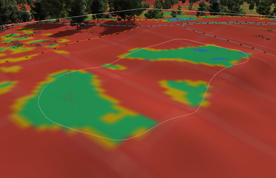
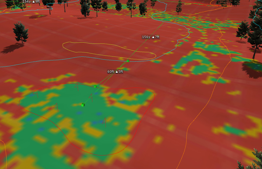
I found many greens this way on The Sand Slopes, including the 5th hole where I shaped a green just on the other side of a hill to form an approach and green site similar to an Alps hole. Pictured below is the slope map prior to any modification of the LiDAR data import and how I outlined the green to fit the more level areas just on the other side of the hill.
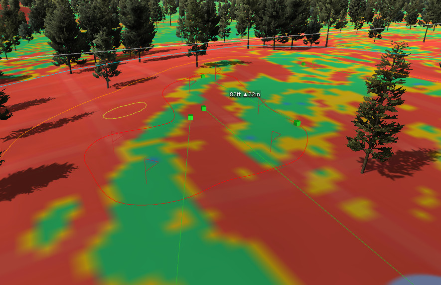
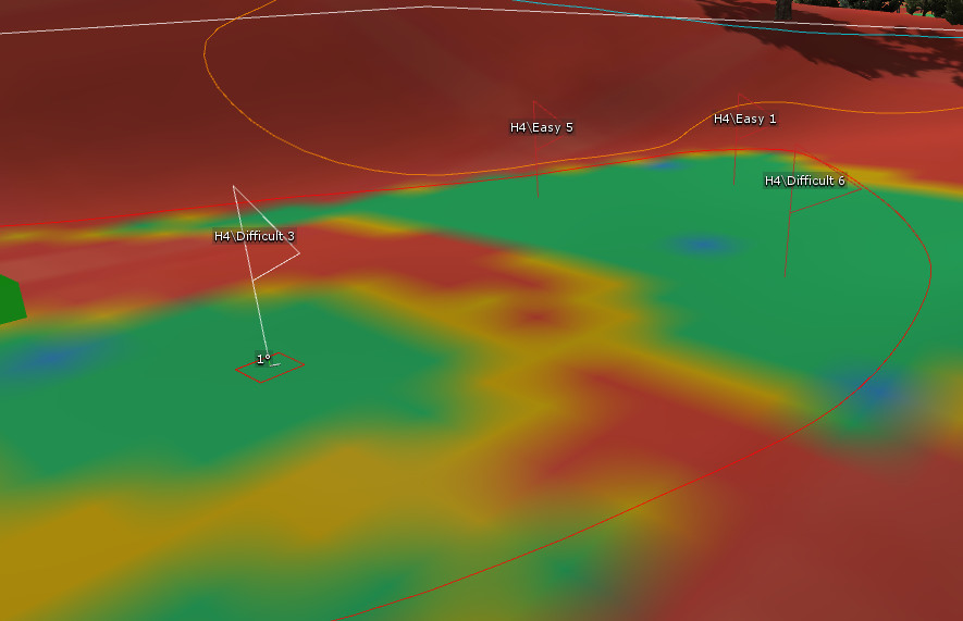
No matter how good your green site location is, some shaping and contouring is required. For my 6th hole on The Sand Slopes, I found this location good for a Double Plateau green site, with the front right a few feet lower than the back right and front left. The primary work I needed to do on this one was to make the pinable areas larger on the left and back.
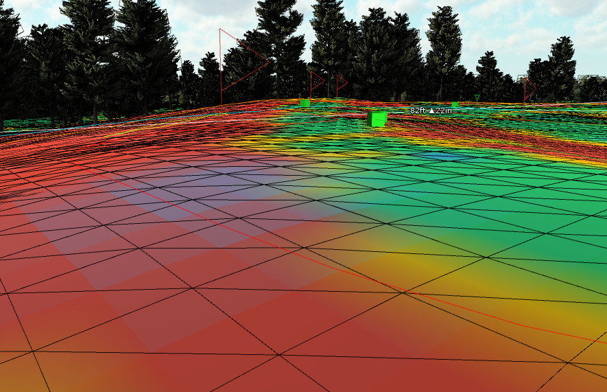
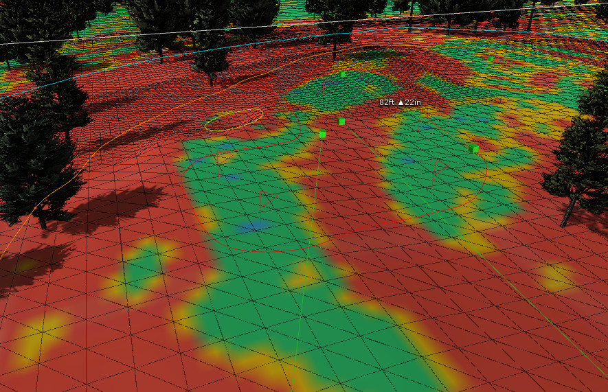
I do not find the flatten elevation tool in Unity very useful for this task. It tends to turn areas blue after regenerating the slope map, signifying the area becomes too flat. Instead use the raise/lower tool with a 5-15 brush size (typically 10) and opacity of 5-15 (typically 10) and use a series of clicks to raise or lower the red areas on the green as needed to make the area more level. I find clicking and dragging does not provide enough control to make these fine adjustments, even on lower opacity settings. Turning on Shaded Wireframe and moving the camera to a low side angle of the terrain helps in visualizing when it is starting to look more level.
Due to the requirement of generating the slope map for the entire terrain, updating it after every adjustment is too time consuming. Try to get the entire green looking as close as possible to the final outcome desired before regenerating the slope map. Once you regenerate, typically there are some unexpected areas of yellow or red remaining or new ones that pop up. It usually takes a few iterations of adjusting the terrain and regenerating the slope map before you get it right. This part is a little annoying sometimes due to the slowness of regenerating the slope map. This guide may receive an update in the future if I find a faster solution to this problem.
Once the slope map is showing the slopes as you intend them, it is time to smooth. Select the smooth elevation tool, turn the opacity up to 100 and use a brush size of 20. Get the camera low to the terrain and click rather than drag again. If it smooths in a direction you don’t like, undo it and try clicking in a slightly different position. Through a series of clicks, cover the entire surface of the green with the brush at least once. If a section of the green looks particularly uneven, hit it with a few extra clicks on a smaller brush size. This smooths out unevenness and makes for a more uniform putting surface without quick changes in break over small areas.
Once your green is shaped and smoothed, or if you are using LiDAR for a real course and your green is already shaped, you’re ready to use the slope map for pin placement. Try to keep you pins at least 5 feet away from anything yellow. Use the BLI tool as well to provide reassurance that the slope you are placing the pin on is appropriate. If the BLI tool comes up 3° or more in an area where the slope map shows less than this, the most likely cause is a bit of unevenness too small to show up on the slope map. Use the smooth tool a bit more on the area and try placing the pin again.
Once you’re done using the tool, remove the color textures from the terrain and don’t forget to delete the _SplatMapGenerator folder in the Assets folder to allow successful builds of your course again. You still need to test your pins by playing them but this method removes a lot of the guess and check. Chances are very few, if any, adjustments are needed after testing using this method.